
21 Jul FUSION 360 TO MACHMOTION CNC MILL OR ROUTER CONTROLS
FUSION 360 TO MACHMOTION CNC MILL OR ROUTER CONTROLS
Fusion 360 to MachMotion CNC Mill or Router.

Post Your CAM G-Code from Fusion 360 to MachMotion CNC Mill or Router
Welcome to another MachMotion minute! In this article we will be talking about how to: post a G-code file from Fusion 360 to a MachMotion CNC Router or Mill Control unit.
Overview
We will be walking through the basic CAM on a Fusion 360 to MachMotion Retrofit CNC Router or Mill Kit!
Starting with downloading Fusion 360, downloading the Mach4 postprocessor, adding a postprocessor to your MachMotion control, creating a toolpath, loading the G-code file, and running a simulation…Let’s get started!
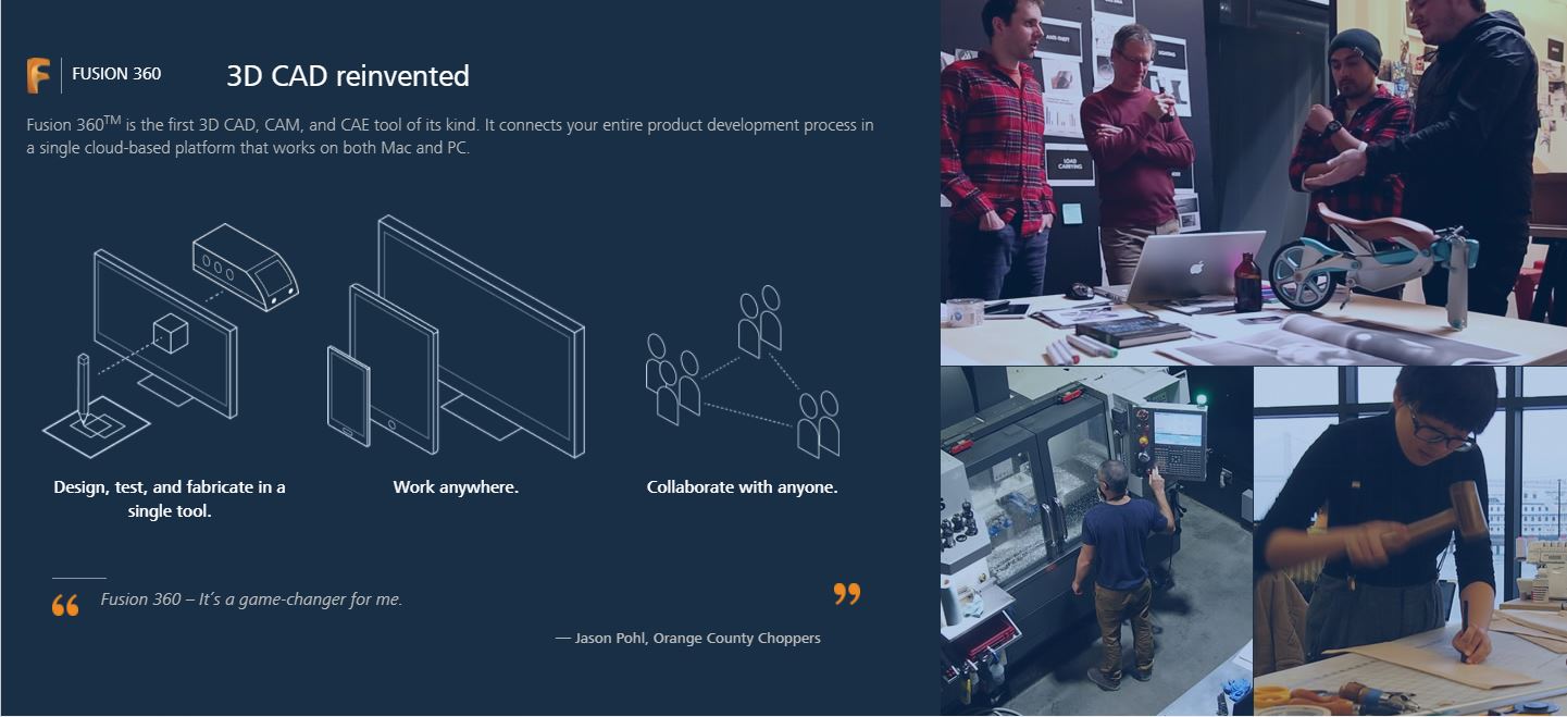
About Autodesk Fusion 360
Autodesk has developed a cloud-based 3D CAD/CAM and CAE software platform for product development. The software is capable of industrial and mechanical design, simulation, collaboration, and machining.
Autodesk Fusion 360 is free if you are a small business making less than $100,000 per year or an enthusiasts, hobbyist or student using it for non-commercial purposes or education.
For more information or to download the software on a PC or Mac, please visit Autodesk Fusion 360
Source Files
If you would like to follow along we have provided you the source files, along with additional resources you will need to get started. The files are available for download here, click the top right blue button labeled “download” and then open up the file in Fusion 360.
Fusion 360 allows for an entire work process and collaboration with sync and timeline support for your projects. Data can both be saved locally and remotely to prevent any loss of progress or data. Every time you save, the system will attach a version number and store the file; at any point you can compare changes between the two versions and merge the changes at any time.
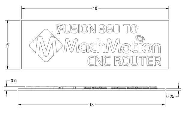
CAD Files and Blueprints
You can easily create 2D drawing from a 3D model, which enables you to generate PDF, DWG and DXF documents. This is also a great way to describe measurements. Our measurements for the logo is 18 X 6 X 0.5 inches, this would also be our minimum stock size.
CAM SHAZAM!
Let’s get started by opening up our “Logo Cut” file. First thing we will do is change our work space, as Fusion 360 allows us to Sculpt, Model, Patch, Simulate and much more. We need to change our work space to CAM. In the upper left, click the Workspace menu and change it to CAM.
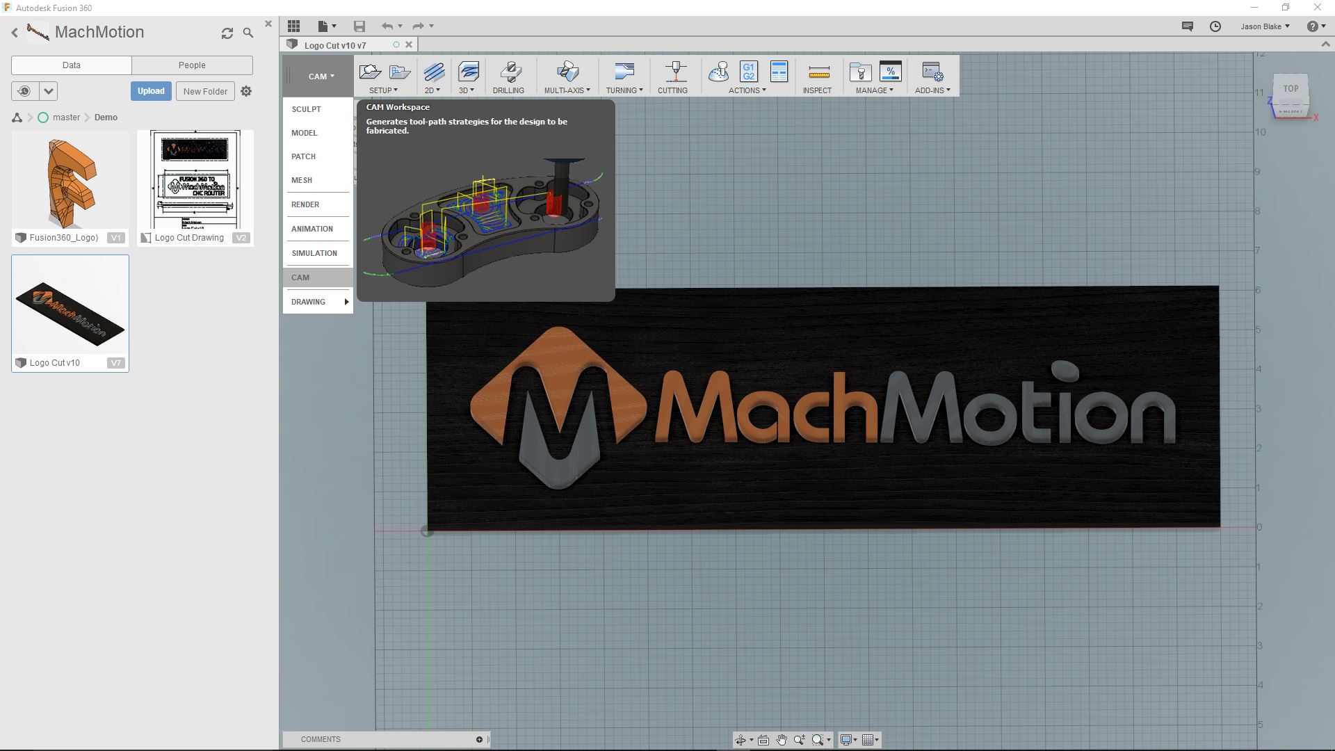
Now we will setup and create our toolpaths. There are a number of different modes ranging from 2D, 3D, drilling and much more. We will start out simple and create a 2D Adaptive Clearing operation.
Under the 2D menu hovering your mouse over the different options and you will notice a small popup showing you a brief description of what the toolpath will do along with an image. Choose the “2D Adaptive Clearing” option.
You will see a window to the right with 5 steps, these steps are always the same to keep things easy to remember.
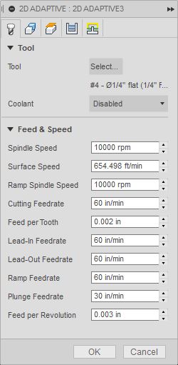
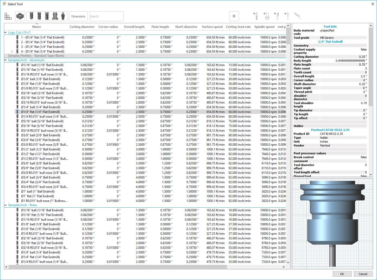
It Starts With a Tool Selection
Let’s choose our tool, click the “Select…” button and a list of available tools will open up. Let’s choose “Sample/Inch – Aluminum 1/4″ Endmill”. Depending on your machine setup you might change the other setting on this tab, but for now we will move on to the second tab, Geometry.
Choosing the Right Geometry to Generating a Success Toolpath
Fusion 360 is intuitive and will give you a yellow box around the part to be machined. For a facing operation we don’t need to select any geometry, but in our case we need to select the area we want to clear, let’s click the wood base. We will now have blue lines indicating the tool’s path, click the Ok button. We now see a 3D representation of the tool including the collet.
Simulate Twice, Cut Once!
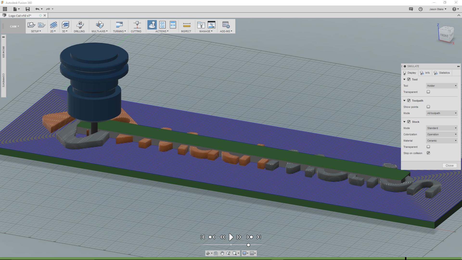
Simulations are the most underrated and underused software technology in CAM but the most important function to utilize. If you take the time to setup your simulation environment, it can save a lot of broken tools and wasted material. Fortunately, Fusion 360 makes it very easy and a topic we will cover in another article. Let’s click the “Simulate” button under “Actions”.
Let’s show our stock material by checking off the “Stock” option in the right side window. Now let’s click the play button at the bottom of Fusion 360 to watch the simulation. If you’ve setup vises and your machines build plate, you can check off the “Stop on collision” to notify you if you’re going to crash. Another helpful function is the simulation can jump to any point in the timeline by clicking your mouse at the point you want it to jump too, like a YouTube video timeline works.
Post Processor Perfection
Post processors are like American accents, each one might sound a bit different but they will all follow the standard English language or in the case of G-Code ISO standards.
The post processor file is one of the most important steps to get right. The reason being it is essentially converting what we see on our computer into G-code and that is all the machine really cares about. MachMotion has spent a lot of time working with the post processors and has a team of experts that make sure our post processors work well with your MachMotion products.
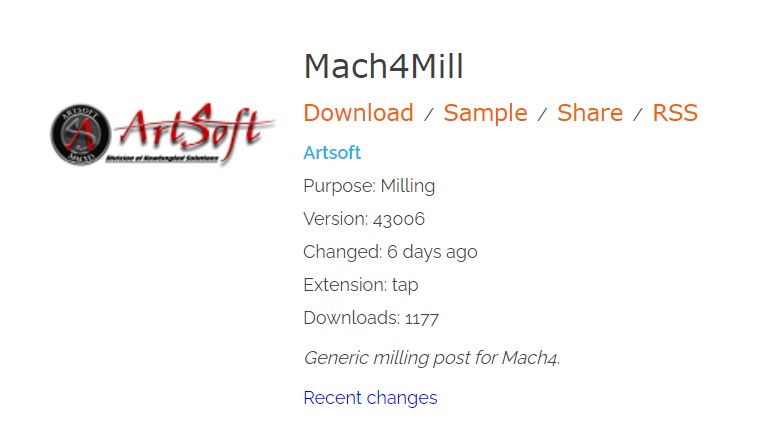
We will first go to Autodesk’s post processor library and download our Mach4 post processor. To make it easy to find, type in “Mach” in the search box and then click the download text below the “Mach4Mill”.
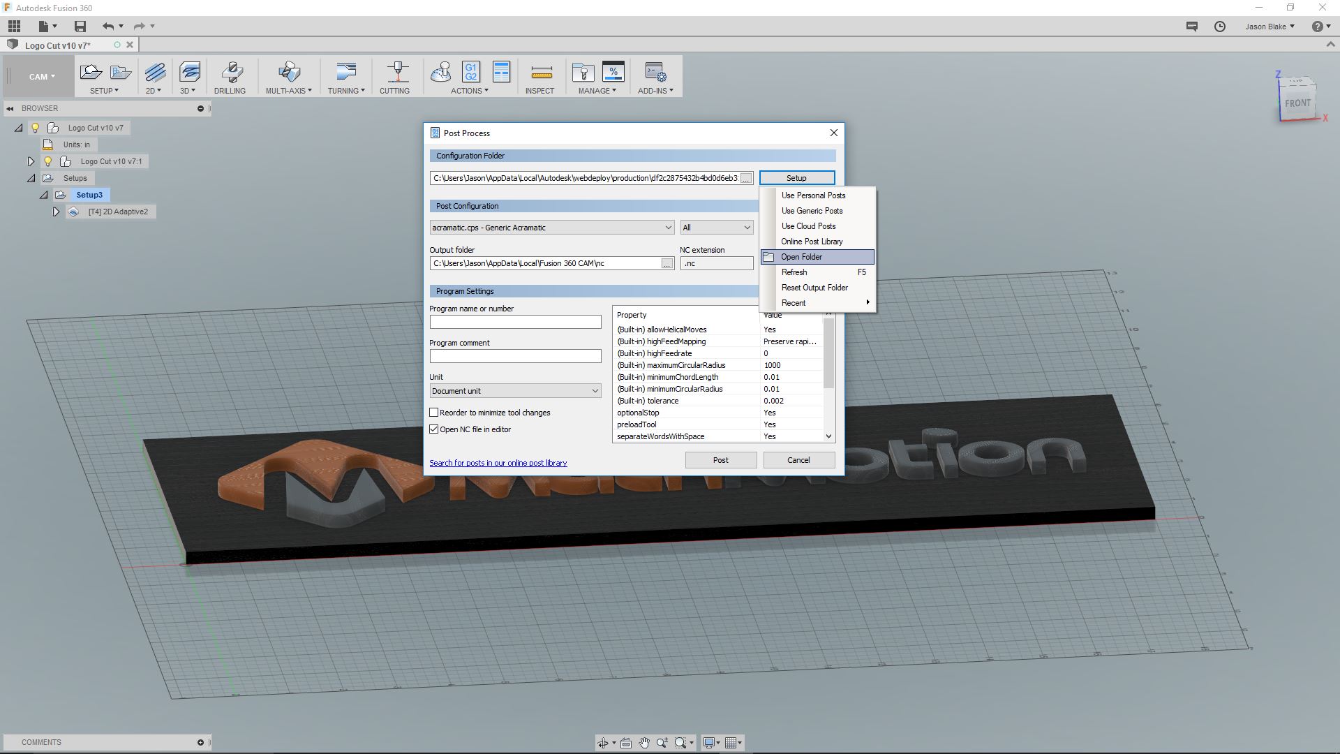
Now that we have our mach4mill.cps go to the top of the CAM menu you will click the “Actions” panel and select “Post Process”.
Click the “Setup” button and from the dropdown list choose “Open Folder”. Drop your mach4mill.cps into this folder.
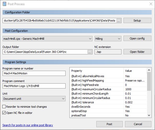
Choose “Mach4Mill” as your post processor from the “Post Configuration” drop down menu.
Type a name “Program name or number” and optional comments, in a later video we will go over all of the different ways you can modify the Post Processor to fit your machine. Let’s click the “Post” button to create the Gcode file.
Post G-Code to MachMotion CNC Router Kit
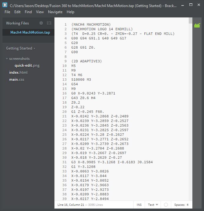
Autodesk Fusion 360 uses Brackets – Interactive Linter as a G-code viewer/editor. It’s kind of like Notepad++. Do a quick overview of the code to make sure everything looks correct, we will be doing another simulation in Mach4 before we run our part.
Let’s Make Some Wood Chips!
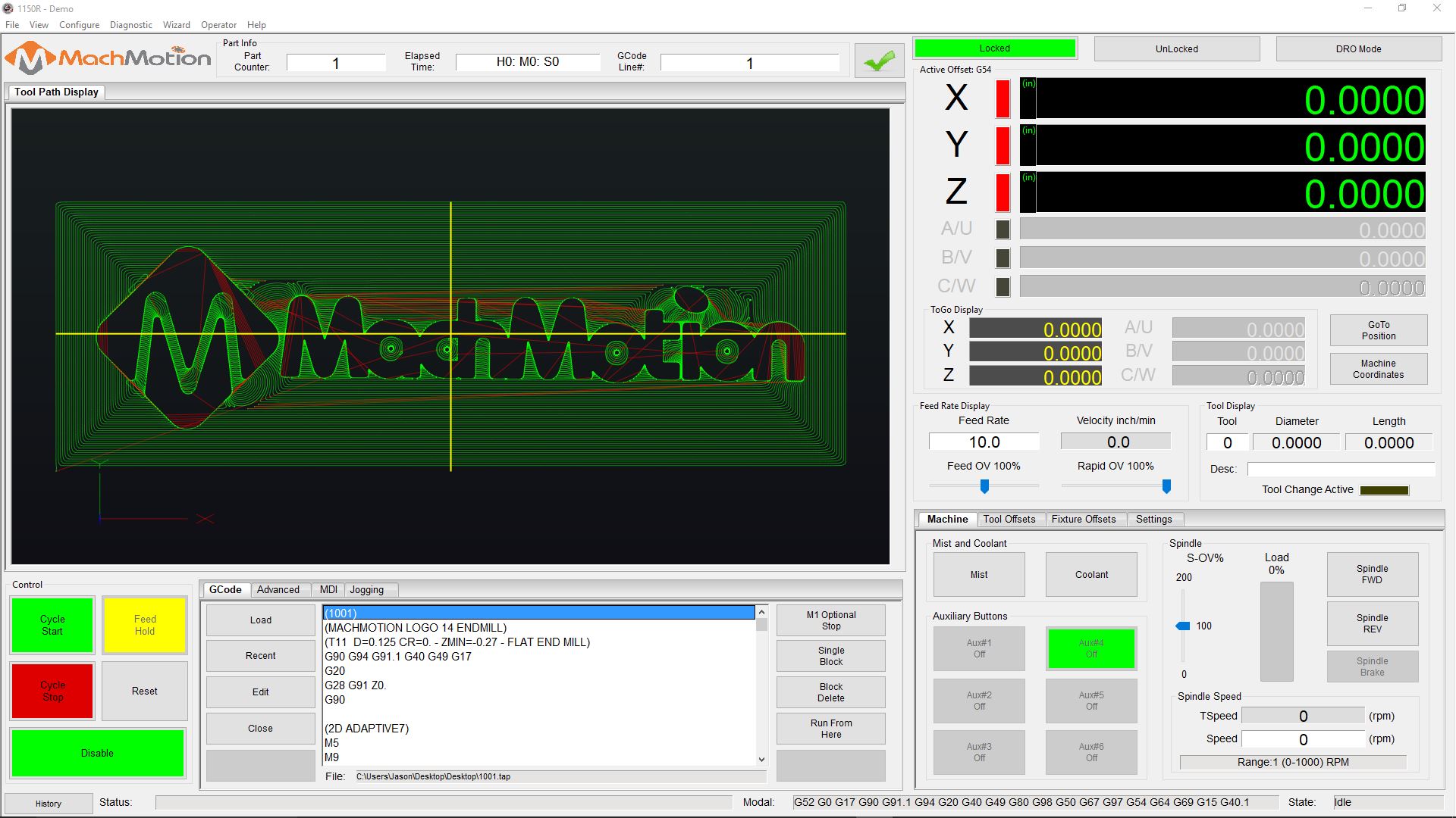
I like to use a USB drive to transfer my Gcode file to my machine’s computer, but in a later article we will show you how to setup a wireless file transfer.
Find the .Tap file that you named and created from the last step. Drag and drop this file to your USB drive and insert the drive into your computer. Startup Mach4 and load the Gcode file. You’re done and chips are flying!
References:
Author: Jason Blake
MachMotion CNC Router Control Kit
Newfangled Solutions
Autodesk Fusion 360
Fusion 360 Post Processors