
29 Jan WHAT IS CUTTER COMPENSATION
WHAT IS CUTTER COMPENSATION?

What Is Cutter Compensation?
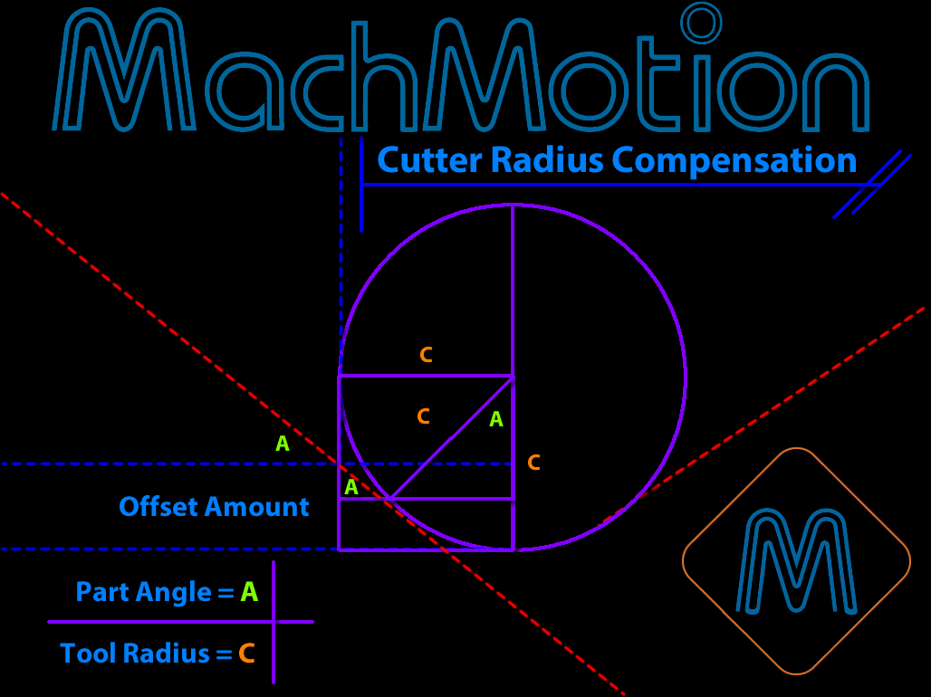
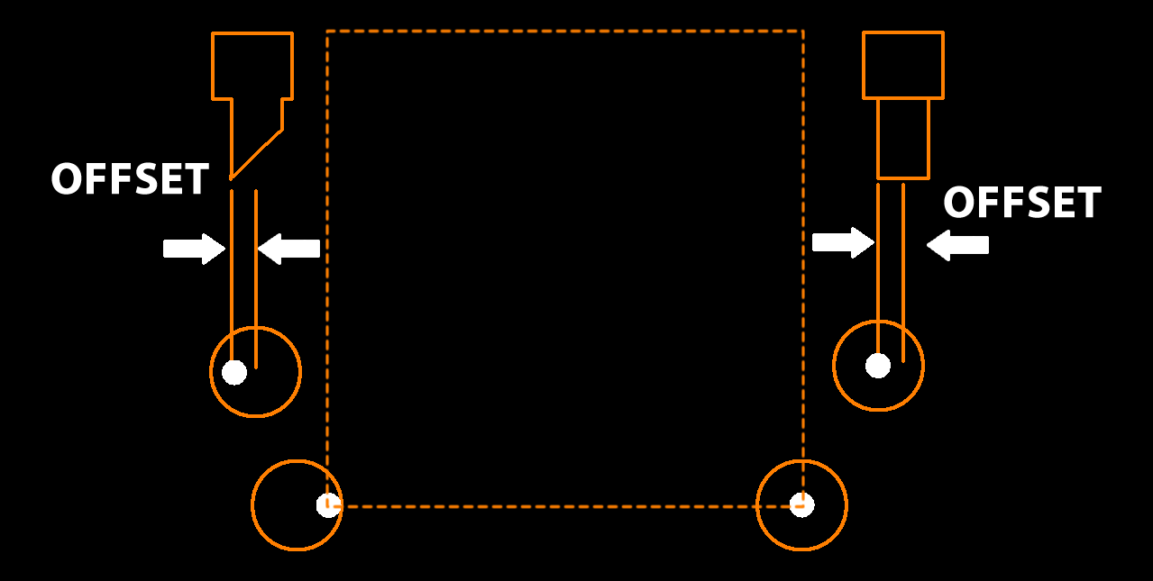
Cutter compensation or sometimes referred to as “cutter comp”, is an offset or shift from center line of the tools shaft to the cutters edge along a programmed path. The advantage of cutter compensation is the use of geometry based offsets rather than tool center point, allowing for the same program to use different diameter tools.
Command names for cutter compensation:
• Tool cutter compensation
• CNC cutter compensation
• G41 G42 cutter compensation
• Cutter diameter compensation
• Cutter radius compensation
• CRC
• Line left
• Line Right
WHEN TO USE CUTTER COMPENSATION
Even if your tool, G Code and machine are running top notch, you might have a slight tolerance issue after measuring your part. This is when cutter compensation allows for those minor adjustments. Rather than regenerating all the Gcode with the new tool diameter, cutter comp allows for you to enter in the new diameter at the machine without changing the Gcode. Uncalibrated or poor alignment of tools can be resolved with cutter compensation to recalibrate the position of all tools without having to reorganize the tools themselves.
Another reason for cutter compensation is programming to the tool tip center. This means that coordinates in the program do not reflect the actual tool cutting edge coordinates. These coordinates are based on the tool tip center rather than on the parts dimensions.
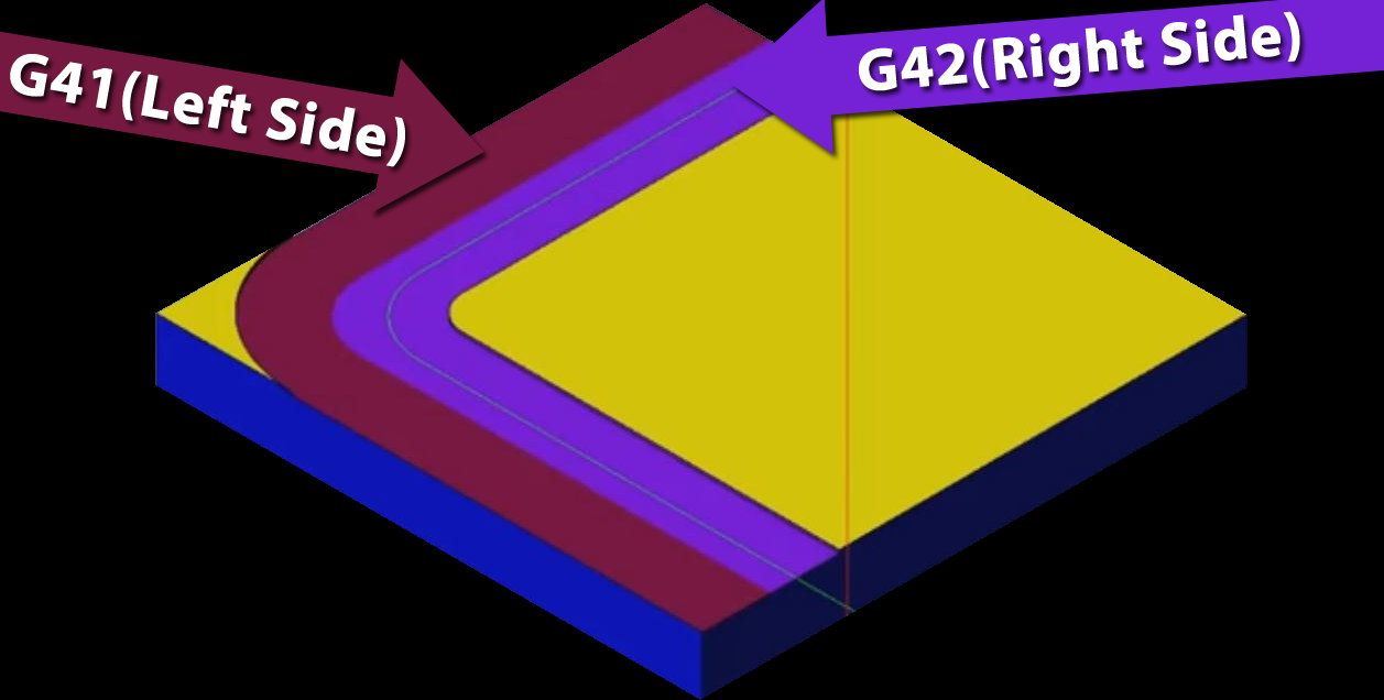
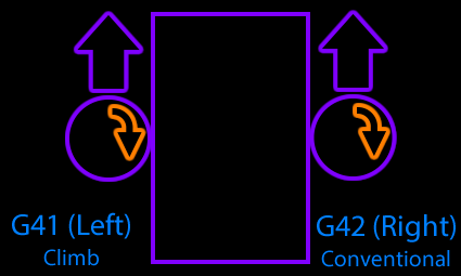
CLIMB (G41) OR CONVENTIONAL (G42) CUTTER COMPENSATION
G41 is used for a left climb with a right-handed cutter direction, while G42 is used for a right conventional approach but what exactly does this mean? G41 will compensate to the left-hand side of the programmed path from the radius of the tool while, G42 will have the tool move along the right-hand side of the programmed path to compensate for the radius of the tool.
*Bonus did you know: Cutter Comp resolved issues to programmers that could take hundreds of hours because of complex contouring.
HOW TO USE CUTTER COMPENSATION
• To turn cutter radius compensation off, program G40 (It is OK to turn compensation off when it is already off).
• Cutter radius compensation may be performed only if the XY-plane is active.
• To turn cutter radius compensation on left (i.e., the cutter stays to the left of the programmed path when the tool radius is positive), program G41 D~
• To turn cutter radius compensation on right (i.e., the cutter stays to the right of the programmed path when the tool radius is positive), program G42 D~. The D word is optional; if there is no D word, the radius of the tool currently in the spindle will be used. If used, the D number should normally be the slot number of the tool in the spindle, although this is not required. It is OK for the D number to be zero; a radius value of zero will be used.
• G41 and G42 can be qualified by a P-word. This will override the value of the diameter of the tool (if any) given in the current tool table entry.
It is an error if:
¨ the D number is not an integer, is negative or is larger than the number of carousel slots,
¨ the XY-plane is not active,
¨ cutter radius compensation is commanded to turn on when it is already on.
The behavior of the machining system when cutter radius compensation is ON is described in the chapter of Cutter Compensation. Notice the importance of programming valid entry and exit move
*Bonus did you know: The terminology used with Dimensional Tool Offsets remains universal between controllers.
Explanation of CNC G-Code:
• G00: Rapid traverse.
• G54: Zero Offset
• G64: Continuous path.
• G90: Absolute dimensioning.
• G17: X/Y plan selection.
• G41: Cutter radius compensation activation (left hand side movement) Climb .
• G42: Cutter radius compensation activation (right hand side movement) Conventional
• G40: Cutter radius compensation de-active
• S: Spindle speed
• F: Axis motion feed
• M: Cutter rotation (3=clockwise, 4=anti-clockwise)
• D: Tool offset no
Explanation Cutter Compensation:
1. N5 G00 G54 G64 G90 G17 X20 Y-20 Z50
2. N10 S450 M03 F250 D01 (12.5 MM DIA)
3. N15 C0
4. N20 Z5
5. N25 G01 Z0
6. N30 Z-5
7. N35 G41 X0 Y0
8. N40 X-48
9. N45 X-68 Y72
10. N50 X-28
11. N55 Y44
12. N60 X12 Y32
13. N65 X0 Y0
14. N70 G40 X20 Y-20
15. N75 G00 Z50
16. N80 Y100
N85 M30
EXAMPLE OF CUTTER COMPENSATION
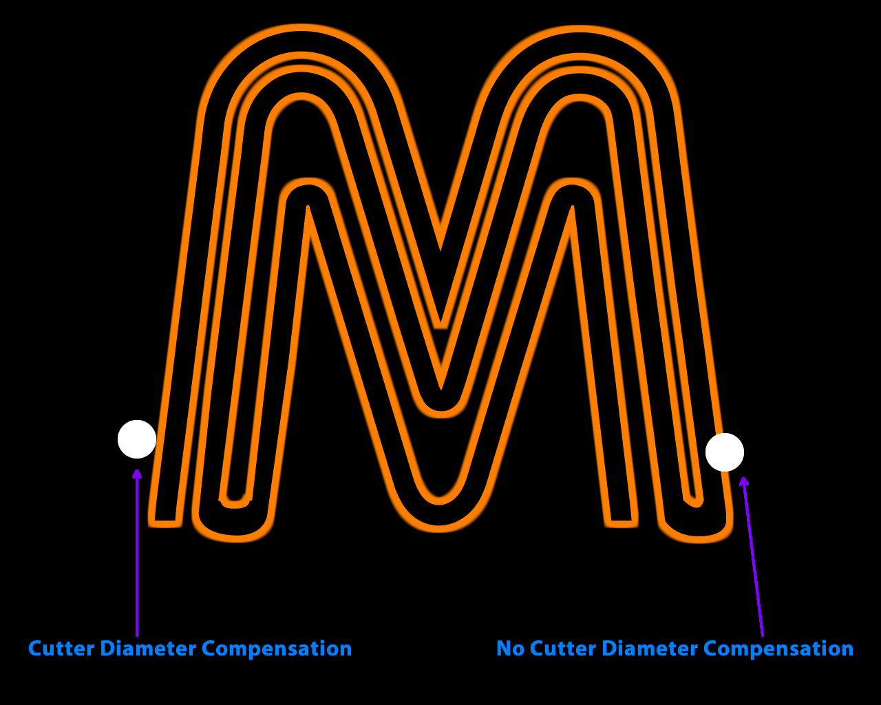
Cutter compensation provides the user with the ability to adjust the tool path for variations in tool cutter diameter.
It can be used in two ways:
First, when programming by hand, without the aid of CAM (Computer Aided Manufacturing) software, it is much easier to program the actual part dimensions, part line programming. This saves the programmer for having to calculate to correct path at the center of the tool when the edge is doing the cutting.
When given a proper diameter offset, cutter compensation will make the appropriate tool path adjustments to cut the part correctly. Essentially the machine does the math for the programmer.
vSecond, with the more widespread use of CAM systems the tool path is already adjusted for the tool diameter and the part should, in theory, be cut perfectly to size. In practice however, there are many factors that determine the finished size of a machined part, cutter and machine deflection, machine positioning accuracy, cutter diameter variations, etc. Cutter compensation allows for fine tuning the tool path, and adjustment of part dimensions, without having to change the program itself.
There are two G codes used to enable cutter compensation.
G41 offsets the tool to the left of the tool path and G42 offsets the tool to the right of the tool path. This is only true for positive diameter offset values. If negative offset is specified the offset direction will be reversed, see figure 28.
There are two ways to call the offset value with G41 and G42.
Format 1: G00/G01 G41/G42 D__ X__ Y__ F__
Format 2: G00/G01 G41/G42 P__ X__ Y__ F__
Use D to call a diameter offset from a specific tool offset number.
For example, D2 will use the diameter offset value of tool offset number 2.
An alternative is to use P. The value specified with P will be the actual offset value. For example, P.05 will offset the tool path .05 to the left or right.
Cutter compensation only works on the two in plane axes, so for G17 (XY plane) the X and Y axes are affected by the comp, G18 ZX and G19 YZ.
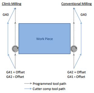
Figure 28 Cutter Compensation Offset Direction
There are two types of milling, which style is used determines how the tool should be compensated. The two types are climb milling and conventional milling, see figure 28.
Conventional milling is the standard in manual machines, but with CNC it is recommended to climb mill when possible.
This manual will assume the tool will always be climb milling. With that assumption if G41 is used for outside features, the profile of a part, then a positive offset will make the part bigger and a negative offset will make the part smaller.
For inside features, a hole, G42 will make the hole bigger with a positive offset and smaller with a negative offset, see figure 29. This method tends to make the offset values more intuitive for the operator.
If conventional milling is used, this description will be reversed.
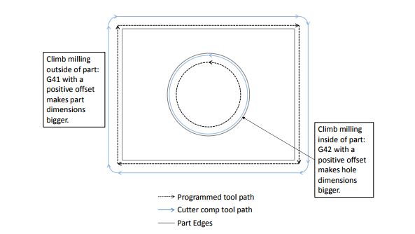
Figure 29 Cutter Compensation OD and ID features
Cutter comp should be enabled on a linear lead-in move; an error will be produced if cutter comp is enabled in a block with an arc.
If there is a value other than zero in the offset then this lead-in move may not be parallel to the programmed path, see figure 28, 34 and 35.
The end point of the start block is the point at a 90° angle to the movement in the next block and at the offset distance. See figure 30 for examples.
This linear move must be longer than the offset amount, if it is not there will be an error. Also, if there are any segments of the tool path shorter than the offset amount a gouge is likely, see figure 31.
The tool path display in Mach will display the actual tool path with comp, check to make sure there are no gouges or abnormalities before
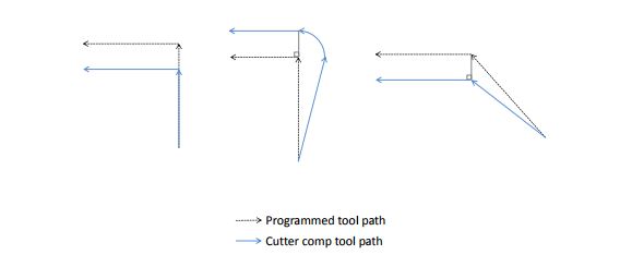
Figure 31 Cutter Compensation Radius and Gouge
Tool Path 1: No cutter comp
G00 G90 G54 G17 G40 G49 G80
G0 X0 Y0 Z1.
S1000 M3
G1 G41 P0 Y.5 F25.
X1.5
Y.6
X2.0
G40 Y1.25
M30
Tool Path 2: Comp radius .05
G00 G90 G54 G17 G40 G49 G80
G0 X0 Y0 Z1.
S1000 M3
G1 G41 P0.05 Y.5 F25.
X1.5
Y.6
X2.0
G40 Y1.25
M30
Tool Path 3: Comp radius .15
G00 G90 G54 G17 G40 G49 G80
G0 X0 Y0 Z1.
S1000 M3
G1 G41 P0.15 Y.5 F25.
X1.5
Y.6
X2.0
G40 Y1.25
M30
Figure 31 shows three tool paths generated by the same program with different cutter compensation offset values. The gouge is created when an offset value greater than the step of .10 is input. When this happens the compensated tool path over laps and is reversed, causing a gouge.
Another example of this is in small grooves as shown in figure 32.
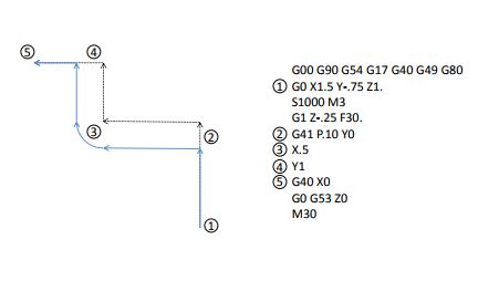
Figure 32 Cutter Compensation In Narrow Groove
Cutter compensation is cancelled by specifying G40 in the program, or when the control is reset.
When G40 is specified it should be on a lead-out move following the same rules as when compensation is enabled. The path will be determined as shown in figure 30. Errors will occur if the lead-out distance is smaller than the offset amount or if G40 is specified on a block containing an

Figure 34 G41 Cutter Compensation Path
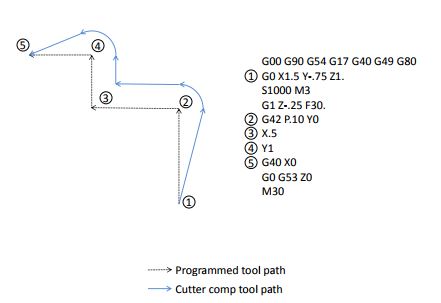
Figure 35 G42 Cutter Compensation Path
CONCLUSION
Most of the time the common approach is to let the CAM system compensate based on the diameter of the tool, and generate the passes in the Gcode. If you are running the same program repeatedly, you might take the G41 or G42 approach as you can easily measure the diameter of the tool and enter in the new value.